Crank and Slotted Lever Mechanism: A Comprehensive Guide
Introduction
The crank and slotted lever mechanism is a versatile mechanical device that converts rotary motion into linear or reciprocating motion. It finds applications in various industries, including automotive, manufacturing, and construction. This article provides a comprehensive overview of the crank and slotted lever mechanism, including its design, working principle, applications, and troubleshooting techniques.
History and Background
The crank and slotted lever mechanism has been utilized for centuries, with its earliest applications found in ancient water pumps and windmills. Over the years, the mechanism has undergone numerous modifications and improvements, resulting in its widespread usage in modern machinery.
Design of Crank and Slotted Lever Mechanism
Components:
-
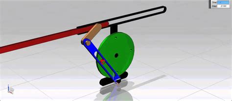
Crank: A rotating shaft or disk with a pin or offset attached
-
Slotted Lever: A lever with a slot or guide through which the crank pin moves
-
Connecting Rod: A link connecting the lever to the output end of the mechanism
Working Principle:
As the crank rotates, the crank pin slides through the slotted lever, causing the lever to oscillate or move back and forth. This oscillatory motion is then transmitted to the output end of the mechanism via the connecting rod.
Types of Crank and Slotted Lever Mechanisms
There are two main types of crank and slotted lever mechanisms:
-
Single Crank Single Lever Mechanism: A single crank rotates a single lever, resulting in a single output motion.
-
Double Crank Double Lever Mechanism: Two cranks rotate two levers, producing two independent output motions.
Applications of Crank and Slotted Lever Mechanisms
The crank and slotted lever mechanism is used in a wide range of applications, including:
-
Automotive: Engine valve actuation, wiper systems, power steering
-
Manufacturing: Industrial presses, material handling equipment, textile machinery
-
Construction: Excavators, cranes, bulldozers
-
Others: Pumps, compressors, musical instruments
Design Considerations
Several factors must be considered when designing a crank and slotted lever mechanism, such as:
-
Stroke Length: The distance traveled by the output end of the mechanism
-
Speed of Rotation: The rate at which the crank rotates
-
Output Force: The amount of force required at the output end
-
Materials: The materials used for the crank, lever, and connecting rod
Troubleshooting Common Issues
Common issues associated with crank and slotted lever mechanisms include:

-
Excessive Noise and Vibration: Typically caused by worn or damaged components
-
Binding or Sticking: May indicate lubrication issues or misalignment
-
Reduced Output Force: Could be due to excessive friction or overloading
Effective Strategies for Troubleshooting
To effectively troubleshoot crank and slotted lever mechanisms, follow these strategies:
-
Inspect Components: Check for wear, damage, or misalignment.
-
Lubricate Components: Ensure that all bearings and moving parts are properly lubricated.
-
Adjust Alignment: Verify that the crank, lever, and connecting rod are correctly aligned.
-
Monitor Output Force: Measure the output force to identify potential issues.
-
Consult Manufacturer: If troubleshooting fails, contact the manufacturer for assistance.
Step-by-Step Approach to Troubleshooting
Follow these steps to troubleshoot crank and slotted lever mechanisms systematically:
-
Identify the Issue: Determine the specific problem encountered.
-
Inspect Components: Examine the components for any visible damage or defects.
-
Lubricate Components: Apply lubricant to all necessary parts.
-
Adjust Alignment: Check the alignment of the crank, lever, and connecting rod.
-
Monitor Output Force: Measure the output force to verify its adequacy.
-
Contact Manufacturer: If necessary, seek assistance from the equipment manufacturer.
Stories and Lessons Learned
Here are some stories and lessons learned related to crank and slotted lever mechanisms:
-
Example 1: A manufacturing facility experienced excessive vibration in a press machine utilizing a crank and slotted lever mechanism. After inspection, it was found that the connecting rod was worn and needed replacement.
-
Example 2: A construction equipment manufacturer encountered binding issues in an excavator mechanism. Troubleshooting revealed misalignment between the crank and lever, which was corrected by adjusting the mounting bolts.
-
Example 3: A power steering system in an automobile failed due to a damaged crank. The cause was identified as overloading due to incorrect installation.
Common Mistakes to Avoid
To prevent common mistakes when working with crank and slotted lever mechanisms, consider the following:
-
Ignoring Lubrication: Proper lubrication is crucial to reduce friction and wear.
-
Overloading the Mechanism: Exceeding the rated output force can lead to damage.
-
Using Improper Materials: Selecting appropriate materials for the components ensures durability and reliability.
-
Neglecting Alignment: Misalignment can result in binding or excessive vibration.
-
Ignoring Maintenance: Regular inspection and maintenance are essential to prevent potential failures.
Conclusion
The crank and slotted lever mechanism is a fundamental mechanical device with a wide range of applications. Understanding its design, working principle, and troubleshooting techniques is vital for engineers and technicians in various industries. By following the guidelines outlined in this article, you can effectively design, troubleshoot, and maintain crank and slotted lever mechanisms, ensuring optimal performance and longevity.
Tables
Table 1: Key Components of Crank and Slotted Lever Mechanism
| Component |
Function |
| Crank |
Rotates and provides input motion |
| Slotted Lever |
Oscillates or moves back and forth |
| Connecting Rod |
Transmits motion from lever to output end |
Table 2: Applications of Crank and Slotted Lever Mechanisms
| Industry |
Application |
| Automotive |
Engine valve actuation, wiper systems |
| Manufacturing |
Industrial presses, material handling equipment |
| Construction |
Excavators, cranes, bulldozers |
| Others |
Pumps, compressors, musical instruments |
Table 3: Troubleshooting Strategies for Crank and Slotted Lever Mechanisms
| Strategy |
Description |
| Inspect Components |
Check for wear, damage, or misalignment |
| Lubricate Components |
Ensure proper lubrication of bearings and moving parts |
| Adjust Alignment |
Verify correct alignment of crank, lever, and connecting rod |
| Monitor Output Force |
Measure the output force to identify potential issues |
| Consult Manufacturer |
Seek assistance if troubleshooting fails |
